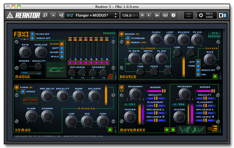
Filter Bank

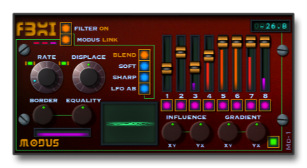
The MODUS LINK switch disconnects the Filter Bank from the MODUS bus turning it into eight variable bandpass kill filters (all faders down no signal will get through).
The 8 stereo filters are made up from 32 single pole high pass and low pass filters, the filters are combined to produce 16 band pass filters, the band pass filters are equally spaced from low to high spanning eight octaves, the position that each filter sits in the spectrum is set by the DISPLACE dial, when MODUS is on the filters will move up and down the spectrum and across the stereo field.
The none-latching buttons below the faders act as a solo for each filter.
MODUS (Modulation Bus)
MODUS modifies the modulation LFO that alters the placement of the FILTER BANK via the DISPLACE dial.
It also has an effect on the FLANGER and the PHASER sections of BOUNCE.
RATE sets the speed of the MODUS LFO, the LFO has three different paths - BLEND - SOFT - SHARP - The fourth path bypasses the MODUS LFO and takes it's signal from the LowFlow Duo built into the SyChrome-FBxi ensemble.
In the stand-alone version of FBxi the fourth path (WALK) randomly crossfades paths 1, 2 and 3.
BORDER limits the hight and depth of the LFO and EQUALITY alters the phase shape of the waveform.
INFLUENCE and GRADIENT have an effect on the signal paths of the MODUS bus.
Bounce
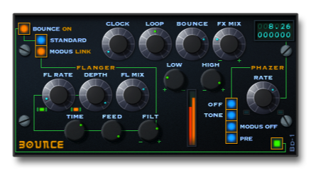
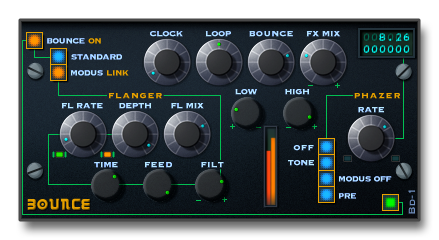
The BOUNCE DELAY receives its signal from the MODUS FILTER BANK, it can be bypassed with the BOUNCE ON switch.
The flanger section of the delay is influenced from MODUS ACTIVITY, by adjusting the FLANGER and the RATE dials you can alter the amount of flanger effect present in the delay signal.
The PHASER is a stereo vintage analog design with a twist, the LFO of the phaser receives its clock source from the MODUS bus, this has the effect of speeding up and slowing down the phaser producing a wah-wah effect, by activating the TONE switch a feedback loop is added to the phaser making the effect produced stronger.
DEPTH, REGEN and DAMPEN effect the sound of the flanger and the BALANCE dial crossfades between the flanger and the delay.
The DELAY time can be adjusted from 0.001ms to 1,500ms for fine adjustment hold down the shift key, selecting the SL switch increases the delay time by a factor of 4, this gives the delay a maximin of 6000ms.
REGEN, BOUNCE, FLOOR and DAMPEN effect the sound and placement of the echoes, the EFFECT dial crossfades between no effect and effect only.
The signal is then passed onto the ATMOS SPACE effect if the parallel switch is set to off.
How BOUNCE and ATMOS are connected to each other is determined with the parallel-series switch, when in series the output of Bounce is connected directly to the input of Atmos, and the two effects run in series, when switched to parallel both effects receive their input from theFILTER BANK, both of the effects are then combined before being passed onto the MOVEMENT processor.
Atmos
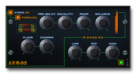
ATMOS receives its signal from the BOUNCE effect, unless the PARALLEL switch is on then it receives it's signal from the Filter Bank, it can be bypassed with the ATMOS ON/OFF switch.
The first process is the pre DELAY, this allows a small amount of space to be place to the front end of the ROOM, the pre delay is stereo and the left and right delay times can be offset with the EQUALITY dial adding a shift to the image.
Next is the 3 BAND EQ, the equalisers are wired in parallel, the first is a 1 pole LOW shelf filter, the second is a 2 pole parametric MID and the third is a 1 pole HIGH shelf filter, each one of the eq's can be set to cut or boost the signal.
The signal then enters the ROOM, this sets the overall size of the space, at the lowest settings and with careful adjustment of the equalisers and filters you can effectively reproduce the body of an instrument, as you move this dial to the right the reflections will become more spaced producing a larger ambience, to tame the room's reflections the DAMPEN dial is used to reduce the high frequencies, to limit the amount of boom that is present adjust the FLOOR dial to the right.
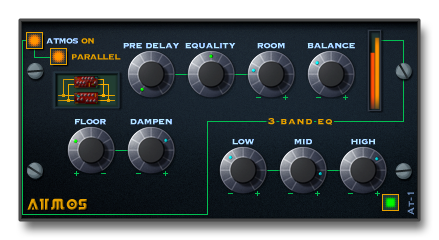
Movement
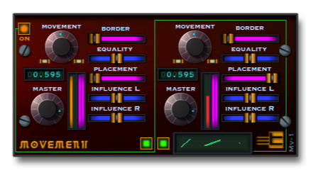
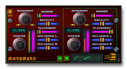
MOVEMENT receives its signal from ATMOS and BOUNCE, it can be bypassed with the ON/OFF switch.
This unit has two independent mono LFO modulated panning circuits allowing the left and right signals to be independently positioned in the stereo field with modulation applied.
The left section process the left signal received from ATMOS and the right section process the right signal.
MOVEMENT will only have an effect if the BORDER fader is above zero, the MOVEMENT dial adjusts the speed of the panner and BORDER effects the width of the stereo environment.
INFLUENCE and EQUALITY alter the phase path of the Panner.
PLACEMENT is used to position the left and right inputs anywhere along the main left and right output paths.
The MASTER outputs are used to set the balance and feel of the stereo image.