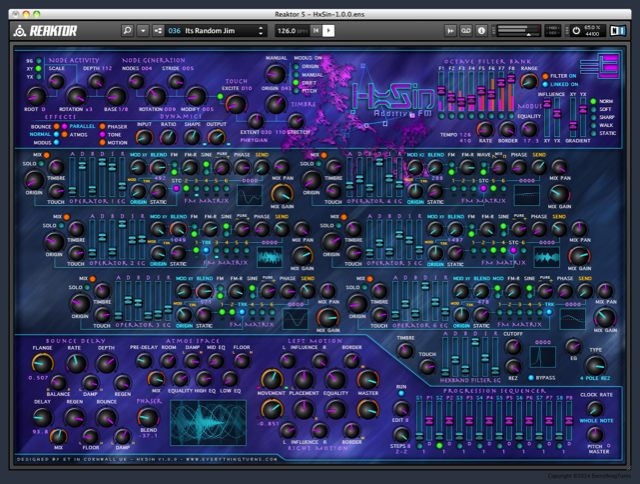
HxSin User Guide
Hover over the image to explore.
The user guide is built into the ensemble and is accessed by selecting the REAKTOR INFO button on the top right, by placing the mouse cursor over each Controller and Text Header of the ensemble, the user guide will pop up.
To use this guide select a page with the buttons above, and then move your cursor over the image, use the return to go back to HxSin's main page.
NODE ACTIVITY.
NODE ACTIVITY.
Think of HxSin as a clockwork music box, first we have the main clock, this is synced to the master tempo in stand-alone mode, or your audio workstation if used as a plug-in.
Attached to this clock is a variable main cog, the cog can be changed in diameter along both the X and Y points in real time, if both points are equal in diameter but have a different ratio to the main clock the Node Generator will run either faster or slower against the main tempo.
If the X and Y points have different diameters to each other then the Node Generator will produce a variable tempo speeding up and slowing down as the cog rotates producing a Yo-Yo effect, and although the tempo is now out of sync with the master clock there will always be a point when it falls in synchronisation with the clock again.
This wobbly cogs shape is determined by the MODUS ACTIVITY and is activated by selecting the 96 XY YX switch next to the SCALE dial, the ROTATION dial is the variable main cog and has 9 different ratio settings.
Now if we attach from 1 to 12 variable cogs to this main cog, each with a gate point and a pitch point determined by a SCALE, then as they each pass the gate point they will generate a note and send it to the OPERATORS, they do this through a synced grid, the grid is determined by the BASE and DEPTH dials.
The way that notes evolve over time is dealt with by the NODE GENERATION section of HxSin and MODUS ACTIVITY plays a big part on how notes are produced.
NODE GENERATION
The NODE GENERATION section determines how HxSin plays the scale generated by NODE ACTIVITY
NODES sets the amount of notes being played together in the chain.
STRIDE, MODIFY and ROTATION adjusts the position between the nodes, altering the points that they will produce a note.
TOUCH sets how dynamically HxSin plays notes, EXCITE and EXTENT are used to set the range, switching on MODUS will activate the modus Bus modulation.
TIMBRE sets the range of notes that HxSin is allowed to play within the scale determined by NODE ACTIVITY.
ORIGIN sets the base note and STRETCH is used to increase the range of notes being played.
TOUCH sets how dynamically HxSin plays notes.
EXCITE and EXTENT are used to set the touch range.
Switching on MODUS will activate the modus Bus modulation.
TIMBRE sets the range of notes that HxSin is allowed to play within the scale determined by NODE GENERATION.
ORIGIN sets the base note and STRETCH is used to increase the range of notes being played, origin and stretch are linked to the modus Bus via the MODUS-ON switch.
MODUS (Modulation Bus)
MODUS is at the heart of HxSin it determines the shape of the cogs in NODE ACTIVITY, it alters the harmonic content of the Operators and it modifies the modulation rate the FLANGER and the PHASER, it also displaces the filters of the OCTAVE FILTER BANK, and allows HxSin to improvise around the root scale being received by the Operators, it's a busy little bus.
There are seven modulation Buses acting within HxSin each one having a different outcome on its destination, a combined visual indication of the bus modulation waveform can be seen in the main output display.
In simple terms MODUS is a low frequency oscillator that influences certain other elements within HxSin in reality it's a bit more complex than that.
The MODUS waveform built from various combinations of eleven sub waveforms generated by four low frequency oscillators, at certain points in this matrix taps are placed picking up the waveform and sending it via the Buses to elements within HxSin breathing life and expression to what would otherwise be quite a static sound.
OPERATORS.
Sine Wave Mode.
HxSin has 6 operators, each producing a pure sine wave and a phase shifted sine wave simultaneously, the balance of the two waveforms can be adjusted with the PURE dial, turning the dial to the left will produce a phased waveform, by rotating the dial to the right the sine wave will become more pure, the PHASE dial alters the amount of phase when PURE is pointing to the left.
Saw - Pulse Wave Mode.
When the operator is switched to WAVE mode the PURE dial will change to MIX, rotating the dial to the left will produce a saw wave, rotating the dial to the right will crossfade over to a pulse wave, the PHASE dial now alters the width of the pulse.
FM MATRIX.
The FM Matrix is used to connect the six operators together to form a chain of modulators and receivers, all operators can be used to modulate any destination apart from self modulation.
By selecting the small button below each number will send the operators frequency via the SEND dial, in order for the destination to receive a signal you need to set the gain of the receivers FM-R dial to a suitable level.
The small indicator LEDs below the buttons show when the operator is receiving a modulator signal.
IMPORTANT.
The FM/MOD button next to the FM-R dial needs to be in the FM position in order for FM modulation to have an effect on the operator.
Selecting the MIX button will send the output of the operator to the main output Bus.
SOLO will mute all other operator mix outputs whilst keeping the FM Matrix sends active.
PROCESSING.
HEXBAND FILTER.
The A-D-B-D-S-R dials effect the shape of the filter, the TOUCH and TIMBRE dials alter how the EG responds to the loudness and pitch of the NODEs being generated.
1 = 2 Pole Low Pass
2 = 2 Pole Band Pass
3 = 2 Pole High Pass
4 = 2 Pole Notch
5 = 4 Pole Low Pass
6 = 1 Pole Low Pass
The CUTOFF dial sets the placement of the filters 1, 2, 3, 5 and 6 if setting 4 is selected the dial is used to position the notch of the filter.
REZ is used to enhance the frequency of the cutoff point by increasing feedback within the filter, this dial has no effect if setting 6 is selected, as the 1 pole low pass filter has no resonant feedback function.
STEREO MOTION.
The STEREO MOTION effect receives its signal from the OCTIVE FILTER BANK, it can be bypassed with the MOTION ON switch.
The top dials process the left signal and the bottom dials process the right signal received from the filter bank.
This is the third stage in the post signal chain and useful for adjusting the overall balance and movement of the stereo image before entering the time based effects.
MOVEMENT will only have an effect if the BORDER dials are above zero, MOVEMENT adjusts the speed of the panner and BORDER effects the width of the stereo environment.
INFLUENCE and EQUALITY alter the phase path of the Panner.
PLACEMENT is used to position the left and right inputs anywhere along the main left and right output paths.
The MASTER outputs are used to set the balance and feel of the stereo image.
The signal is then passed onto the BOUNCE DELAY effect.
BOUNCE DELAY.
The BOUNCE DELAY receives its signal from the STEREO MOTION effect, it can be bypassed with the BOUNCE ON switch.
The flanger section of the delay is influenced from MODUS ACTIVITY, by adjusting the FLANGER and the RATE dials you can alter the amount of flanger effect present in the delay signal.
DEPTH, REGEN and DAMPEN effect the sound of the flanger and the BALANCE dial crossfades between the flanger and the delay.
The DELAY time can be adjusted from 0.001ms to 1,500ms for fine adjustment hold down the shift key, selecting the SL switch increases the delay time by a factor of 4, this gives the delay a maximin of 6000ms.
REGEN, BOUNCE, FLOOR and DAMPEN effect the sound and placement of the echoes, the EFFECT dial crossfades between no effect and effect only.
The signal is then passed onto the ATMOS SPACE effect if the parallel switch is set to off.
The PARALLEL/SERIES switch is used to to change how the two effects are connected to each other, when off the output of the Bounce Delay is connected directly to the input of the Atmos Space, the two effects run in series, when switched on both effects receive their input from the Stereo Motion, both of the effects are then combined before being passed onto the Dynamic processor.
ATMOS SPACE.
The ATMOS SPACE receives its signal from the BOUNCE DELAY effect, unless the PARALLEL switch is on then it receives it's signal from the Stereo Motion, it can be bypassed with the ATMOS ON switch.
The first process is the pre DELAY, this allows a small amount of space to be place to the front end of the ROOM, the pre delay is stereo and the left and right delay times can be offset with the EQUALITY dial adding a shift to the image.
Next are the three stereo equalisers, the equalisers are wired in parallel, the first is a 1 pole LOW shelf filter, the second is a 2 pole parametric MID and the third is a 1 pole HIGH shelf filter, each of the eq's can be set to cut or boost the signal.
The signal then enters the ROOM, this sets the overall size of the space, at the lowest settings and with careful adjustment of the equalisers and filters you can effectively reproduce the body of an instrument, as you move this dial to the right the reflections will become more spaced producing a larger ambience, to tame the room's reflections the DAMPEN dial is used to reduce the high frequencies, to limit the amount of boom that is present adjust the FLOOR dial to the right.
The signal is then passed onto an output limiter (the limiter is always on) and then last in the chain is the DYNAMICS processor.
DYNAMICS.
The INPUT dial sets the compression threshold, and the OUTPUT dial sets the Master Output Gain.
RATIO adjusts the amount of compression being applied to the signal and the SHAPE dial is used to control how fast and the amount of time the compression takes effect.
The signal is then passed onto an output limiter (the limiter is always on).
PROGRESSION SEQUENCER.
The PROGRESSION SEQUENCER is used to add changes to the whole pitch range generated by the NODE GENERATOR, this is an analog style sequencer and will automatically alter its step position as you change the dials.
Each of the steps can be altered from 1 to 64 beats, giving you a maximin of 512 beats over the eight steps, the number of steps can be set from 2 to 8.
The clock that the sequencer is locked to can be adjusted from whole note to a maximum of sixty fourths with the horizontal fader, move the fader left to right to change the clock rate.
The Sequencer clock can be bypassed and any step can be selected with the EDIT dial, this is handy when checking how steps with a high number of beats are altering the pitch of the NODE GENERATOR without having to wait for the sequencer to circle back each time, or you can also use it to set different steps to alternate pitches and switch between them.