PurPLe User Guide
Hover over the images to explore.
The user guide is built into the ensemble and is accessed by selecting the REAKTOR INFO button on the top right, by placing the mouse cursor over each Controller and Text Header of the ensemble, the user guide will pop up.
To use this guide select a page with the buttons above, and then move your cursor over the image, use the return arrow to go back to MoGi's main page.
Free Running Oscillators
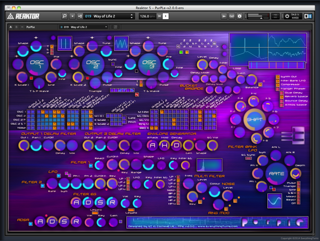
PurPLe has free-running oscillators that deliver a diverse sonic arsenal from 9 waveform generators including sine, triangle, saw and pulse, the waveforms can also be shaped and detuned, plus sync and instability can be added.
Each of the 3 oscillators has soft clip gain reduction, so pushing the output level will brick wall the waveform without inducing distortion.
What sets PurPLe's oscillators apart is that they are capable of generating multiple free running waveforms at the same time, the waveforms can be used as a modulation source in the matrix patcher to modulate other parts of the synth. (you can feed the output from any oscillator back into any oscillator, including itself, giving you very diverse waveform modulation)
Oscillator 1 has a sine-wave generator and a choice of triangle, saw or pulse, the waveforms can be shaped, you can also add a small amount of instability to the mix. (want the sound of an old unstable synth, no problem)
Oscillator 2 has two waveforms both available at the same time, one pulse and one triangle you can shape the waveforms and add instability, you can also detune the pulse against the sine, hard sync to oscillator 1 is also switchable here.
Oscillator 3 is a slightly different beast with selectable triangle or sine waveforms plus a tuneable Pulse waveform, it has a wider frequency range than OSC-1 and 2, you can use it as a low frequency modulator or to add sub frequencies or both, again instability and shape are included.
The Digital Display below the oscillators can be switched between dial mode, where a numerical readout of each dial that is being adjusted is displayed, or Hz mode that displays the frequency of the master outputs in Hz.
Synth Components
NOISE GENERATOR
The Noise Generator is sweepable from pink to white, it can be used as a sound source, modulated and also a modulator in the matrix.
RING MODULATOR
A simple ring modulator, patched in with the matrix patcher. (bell type effect)
MULTI FILTER
The Multi Filter has 4 lowpass filters, a notch filter, 2 bandpass filters and 2 high pass filters all with resonance, the filter can be patched in using the matrix, also the cutoff can be modulated.
BUCKET BRIGADE
The BBD is a single delay unit with four diffuser delays, a 1 pole filter is placed in a feedback loop allowing frequency degradation of the signal. (hi-fi it's not)
The input signal is first saturated and then sent to four chained diffusers with mix and delay size adjustable.
The diffused signal is then filtered by a 1 pole bipolar filter and returned via the single delay unit to form a feedback loop, it can be a tricky beast, but worth playing with as it can knock decades off the sound.
Envelope Generator
PurPLe uses an envelope generator, the EG works a bit different than the standard ADSR used on most synths, there is no release, the decay plays that part instead, and it can self trigger. (the PPe also has 2 standard ADSR's, more on them later)
The Gen control when fully clockwise can be triggered via midi allowing the PPe to be triggered like a midi keyboard, the Matrix Patcher is used to make the connections, the oscillator scale is controlled via the K Scale 1 and 2 dials.
As you turn the Self Gen control anti clockwise it will start to self trigger at regular intervals.
When the EG is triggered via midi or self triggers, it will go through a cycle that is set by the Attack Hold and Decay, if you hold a key down longer or shorter than the cycle, it will still do it’s thing.
Output Delay Filter
The five dials of the Output Delay Filter set the overall sound of the PPe. (this takes a bit of understanding, especially as there are ten dials)
The oscillators of the PPe can have a small amount of instability added, this goes a great way to make the sound evolve over time, especially when two oscillators are playing and drifting against each other.
But that alone is not what makes a synth have its own unique sound. (just makes it sound a bit knackered)
The PPe actually has four output signal paths leaving the matrix patcher, and is split into two pairs, each pair follows two paths. (told you this takes a bit of understanding)
First we have the vintage path, this goes through a simple filter combination, then we have the harder sounding clipper path.
To activate both paths you need to patch both the Main Output(s) and the Delay In(s) on the matrix patcher. (an example of this is in the tutorial workshop bank)
* IMPORTANT *
You always have to patch the main outputs or there will be no sound. (the paths split after the main outs)
By adjusting the cutoff, delay and mix dials you can combine both paths before the pan and gain dials. (still with me?)
The reason for this output configuration is quite simply choice of the overall sound plus it adds a bit of fun to the mix.
As an example you can patch the oscillators through the vintage outputs and the multi filter through the delayed outputs sending a mix of the two from the synth. (the delay has a maximum time of 4000ms)
Or just use the delayed outputs with a zero setting to get a harder sound from the synth. (see the important bit above)
This may seem a bit complex and strange when used for the first time, but its worth pursuing as it allows the PPe produce an extremely wide range of waveforms, even from just a single sine wave.
The Matrix Patcher
Firstly we have 2 patch bays, one for the synth and one for the effects on Panel B. (the effects patcher is referred to as a matrix patch bay)
The patcher is split into five sections, the first is for the outputs of each component of the synth, when selected it will send them to the master outputs. (pre matrix effects)
Secondly is the section for patching the outputs to the inputs of the synth components and is used to join up everything.
The third section is oscillator modulation, giving you a variety of modulation sources, and the fourth section is used to modulate the synth effects and the EG. (not post matrix effects)
The last section is used for controlling oscillator pitch via midi. (see Midi and Key Scale)
If none of the links are patched together no sound will be produced.
Midi and Key Scale
In order to get PurPLe to respond to midi you need to activate the Midi, Gate and Pitch buttons in the Matrix Patcher.
The Midi button lets midi note data in, the reason for this is we can now intercept the midi data and do a few different things with it, the Gate and Pitch buttons are normally selected at the same time.
Next to the midi button are the three OSC to Midi buttons, if selected they will send midi note data direct to the oscillators. (you still have to tune the oscillators)
Next to K Scale 1 and 2 in the matrix are six buttons that allow the midi scale (intonation) of each oscillator to be changed, the K Scale range is set with the dials at OSC-1 and 2, there is no K Scale for OSC-3 but it can follow the others. (when selecting K Scale the oscillator pitch will jump, so you will need to retune them)
Examples of ways to use Midi and K Scale are in the Snapshot Bank Tutorial Workshop under the heading MIDI CONTROL.
Filter ADSR
The new filters and ADSR's of PurPLe v2 take it in yet another direction, making it a more powerful playable synth, you can still create strange and weird soundscapes but now have the ability to shape and filter those soundscapes playing them in a more conventional manner.
Filter one is a variable multimode filter consisting of a resonant low pass - band pass - high pass design with variable two or four pole slope, the filter shape and tone is enhanced with the use of an envelope generator as well as key and velocity via midi.
In addition to having ADSR control of the filter with the Filter EG, the waveform output can also play a part in shaping the contour of the sound.
Filter two is a slightly more conventional filter consisting of a switchable 1 - 2 - 3 or 4 pole low pass design with resonance, again the filter can be influenced via the EG and midi.
Bolted in-between the filters is the LFO modulation, when the LFO waveform is positive it can lift the cutoff of filter one, as the waveform goes into its negative phase it can lift the cutoff of filter two, this produces a gentle or not so gentle sweep of the filters, breathing even more life to the sound.
Last in the chain is the amp ADSR with key and velocity control via midi.
The Matrix Patch Bay
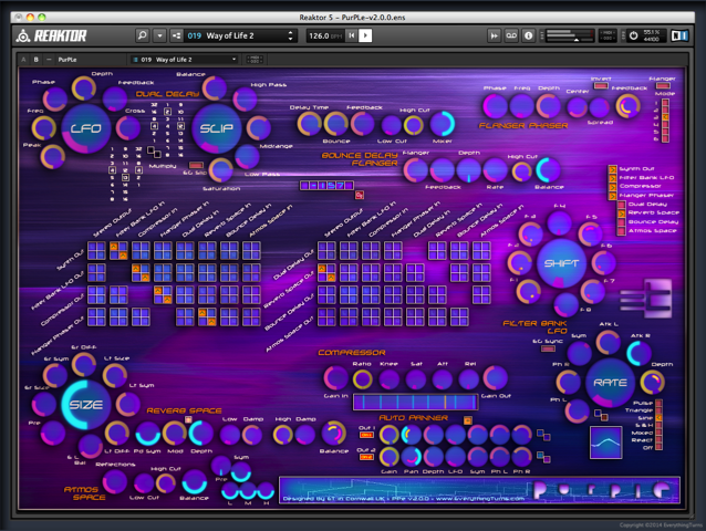
The matrix patch bay allows you to route the post synth effects in any order and has a stereo bus.
The effects are simply chained together out to in, if you've understood the matrix patcher then this will be easy.
You can swap the stereo signals and mono the effects, and they can be patched in parallel or series.
* WARNING *
It is possible to overload Reaktor by adding to many effects to a patch, you have to go with the CPU power that you have - Under no circumstances patch everything in the matrix with Reaktor's CPU power dial set to off and then save your ensemble, you may never be able to load it again. (reaktor starts up with the power on)
Stereo LFO Filter Bank
The filter bank will sync to the EG, free run with a choice of waveforms or the LFO can be switched off turning the filter bank into 8 variable bandpass kill filters. (all dials down no signal will get through)
The 8 stereo filters are made up from 32 single pole HP and LP combined filters (16 left and 16 right), the filters are equally spaced from low to high, the position that each filter sits is set by the Shift dial (LFO phase linked), so as the LFO travels through it's range the filters will move up and down the spectrum and across the stereo field. (if the LFO is synced to the EG the filters will jump in frequency and around the stereo field on each gate pulse.
When using the EG as a sync for the filter bank the phase will sync to the gate trigger, pushing the phase on each pulse, so you need to set the phase and filters to suit the sound.
The Oscilloscope shows you the waveform phase only, and not frequency of the filters, for that you need a pair of ears.
The Vu meters show the amount of left and right gain for each of the 8 filters.
Post Synth Effects
No big description on how the effects work needed here, just a few pointers.
DUAL DELAY
A stereo delay with adjustable left and right cross delay feedback, the Slip dial messes with the delay clock. (the clock will re-stabile once the dial stops moving, but the slip will have been recorded and be repeated as part of the feedback loop.
FLANGER PHASER
Single analog delay seven stage phaser / flanger with LFO offset.
BOUNCE DELAY FLANGER
Stereo delay with variable left and right delay times, linked to a stereo flanger. (the flanger is actually 1st in the chain)
ATMOS SPACE
Stereo reverb with a pre delay and delay symmetry, low - mid - high eq followed by low and high cutoff filters, the pre delay, eq and filters give this reverb the ability to occupy a different space to the signal that it is receiving.
REVERB SPACE
Stereo reverb with independent control of the early and late reflections, plus modulation.
COMPRESSOR
The In dial sets the compression threshold, and the out dial sets the Master Output Gain.
LIMITER
The Automatic Clip Limiter after the Auto Panner is just doing it's thing, no need to worry about it.
Auto Panner
The Panner's are placed before the master outputs and can be bypassed with the small mute switch.
As this is the last stage in the signal chain, the gain and pan dials are useful for adjusting the overall balance of the stereo image, the auto pan will only have an effect on the signal if the depth controls are above zero. (setting the output pans to mono would hi-light any stereo phase problems, adding a small amount of auto pan may resolve this)
The LFO adjusts the movement speed of the panner and depth effects the width and placement.
The symmetry and phase dials adjust the waveform shape of the LFO.
The left and right outputs from the synth enter the panner as two mono signals, allowing you to adjust the stereo width or reposition each channel and adding different amounts of auto pan. (long evolving atmospheres will benefit greatly by adding different amounts of auto pan to each channel producing a slow phasing effect of the stereo image)